Running Man#
In this example, we will demonstrate how to set up a full body simulation using deformable body.
The file we start with can be found here
Step 1: Create Mesh Bone#
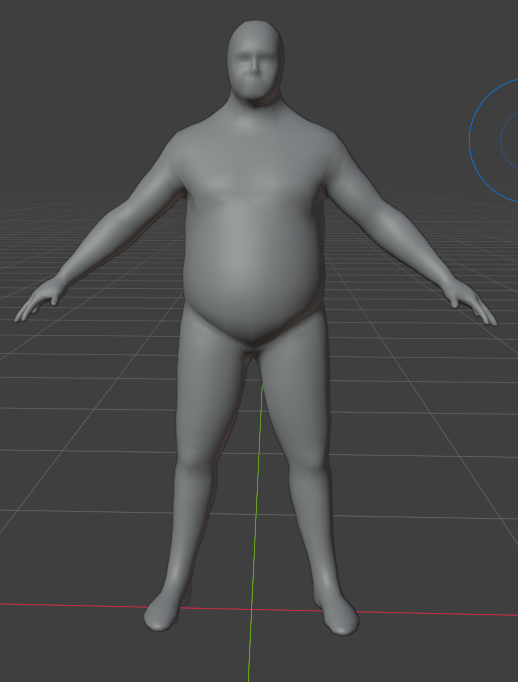
In the Modeling collection, you can find BodyGeo_Orig mesh, it is the body mesh we are going to simulation.
We want to create a simulation of the running man with a jiggling belly. To achieve this, we are going to use the idea of the mesh bone. mesh bone is an mesh that the internal of the deformable body simulation will try to follow (hence the name mesh bone). The more distance the mesh bone has to the surface, more deformation and secondary motion (jiggle) the simulation will have.
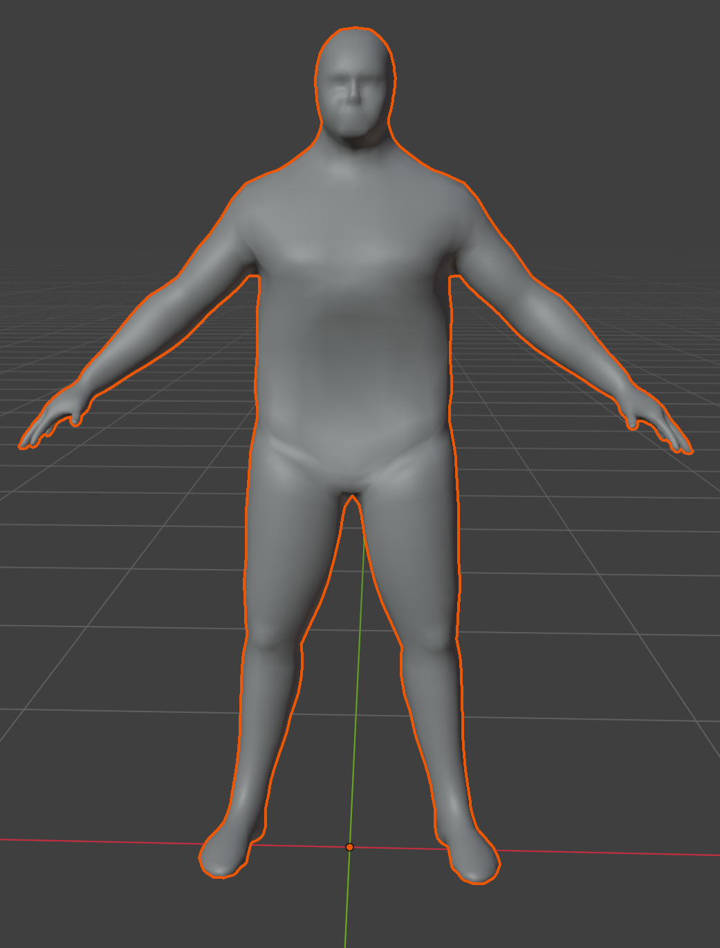
We will start with BodyGeo_Orig, and use the brushing tools to push in the belly region.
-
Select BodyGeo_Orig
-
Goto Sculpt Mode
-
Use Subtract
-
Turn on Symmetry in the X axis
-
Start Brushing!
We provided a BodyBoneMesh_Orig as a reference, this is the mesh bone we used in our setup.
Step 2: Get Animation (optional)#
You can use website like Mixamo to get an animation for the mesh bone. However, in the example file, we already have an animated mesh bone in the Simulation Rig collection. In the following steps, we will use the provided animation as example.
Step 3: Setup Preroll#
- goto frame -30
Negative Frames
If you can't go to frame -30, goto edit->preference->Animation->Timeline, make sure Allow Negative Frames is checked.
-
Select Armature enter Pose Mode
-
Select all joints, and press Alt-R to reset all rotations,
-
Select mixamorig:Hips joint, reset all translation
-
Key all joint
Initial Velocity
The animation has a starting velocity, as the animation does not have a transition from stationary to running. To prevent the sudden motion at the first frame, we need to add a starting velocity to the preroll. The initial velocity can be computed using the first frame displacement of the hip joint and multiply it by 30.
-
Select mixamorig:Hips joint, set the z-translation to -2.41672 m
-
Goto Object Mode, Select BodyGeo joint, set the y-translation to 2.41672 m, so the BodyGeo aligns up with the BodyBoneMesh at frame -30
Step 4: Set Solver#
-
Create an empty plane axis, rename it solver, goto the physics panel, turn on HiPhy, select Lagrangian Solver
-
Change the Newton tolerance to 2.
-
Change the CG tolerance to 2.
-
Change the Start Frame to -30.
-
Change the End Frame to 100.
Step 4: Set Deformable Body#
Before we set the simulation parameters, we need to first subdivide the BodyGeo mesh.
Simulation Resolution for Deformable Body
Unlike other materials, the simulation resolution for Deformable Body is not determined by the mesh resolution, but the Deformable Body Grid Resolution on the solver. HiPhyEngine embeds the simulation into a background grid for simulation. However, the simulation mesh size still determines the collision resolution, so you do not want the simulation mesh to be significantly larger than the simulation grid size.
-
Select BodyGeo, add a subdivision surface modifier, set the subdivision level to 1.
-
Add a Triangulate modifier to BodyGeo, check keep normal.
-
Select BodyBoneMesh, add a subdivision surface modifier, set the subdivision level to 1.
BodyBoneMesh Resolution
The mesh bone does not need to match the vertex count the simulation mesh. However, in our case, for majority of the body, the mesh bone is on the surface of the simulation mesh. In such case, if the mesh bone does not match the simulation mesh, there will be artifact on the simulation mesh after showing the discrepancy between the two meshes. If user is interested, you can skip this step and see the simulation artifact.
-
Duplicate BodyGeo to BodyGeo.Driven, delete the triangulate modifier and apply the subdivision surface.
-
Select BodyGeo, turn on Hi Phy in the Physics panel, choose Deformable Body as the material model
-
select solver for the solver
-
select BodyBoneMesh for the Mesh Bone
-
select BodyGeo.Driven for the Driven Shape
-
Change Friction Coefficient to 0.1. (The arm is constantly rubbing the belly and we don't want them to snag)
Now you can run the simulation and see the result!
Step 5: Make it jiggle!#
The default parameter is for muscle like material, so it won't have much jiggle, to make the character jiggle, we need to turn down the stiffness
- Select BodyGeo, change mu to 100000 (divide the default value by 10), change mu to 200000.
\(\lambda\) and \(\mu\) ratio and incompressibility
The ratio between \(\lambda\) and \(\mu\) defines the incompressibility of the material, specifically the equation is \(\frac{\lambda}{2(\lambda + \mu)}\). As a (very inaccurate) rule of thumb, user can view the value \(1 -\frac{\lambda}{2(\lambda + \mu)}\) as how easy to compress that much volume. That if the \(\lambda\) twice the value of \(\mu\), it means about 30% of the volume can be fairly easily compressed, If the \(\lambda\) ten times the value of \(\mu\), it means only \(10%\) can be compressed. Very incompressible might introduce numerical issues to the solver.
- change mesh bone binding stiffness to 100000 (divide the default value by 10). (We want to loosen up the mesh bone a bit, so the jiggle can propagate a little).
That's it! The final file with can be found here