Elastic Rod#
Elastic rod is the material model for simulating curves. Elastic rod objects in Blender must be curves objects.
Related Objects#
Solver-
The Solver object for the simulation.
Rest Shape-
The Rest Shape is the object for defining the shape at rest. The simulation object will returns to the Rest Shape when there is no external force. When no Rest Shape is specified, the start frame of the simulation object is used as the Rest Shape. Rest Shape needs to have the same number of vertices as the simulation object.
Target Shape-
During simulation, the Target Shape creates a force to pull the simulation object towards the Target Shape. It designed for achieving art directed shape during motion. The strength of the pulling force is controlled Target Stiffness and Target Damping parameter. Target Shape needs to have the same number of vertices as the simulation object.
Driven Shape-
As noted in overview, in Blender, the simulation cache directly deforms the point attribute before any modifier is applied. While during export, all modifiers of the simulation object is applied. This means that having any modifiers on the simulation object that changes point position or vertex count on the simulation object will leads to a discrepancy between the simulation mesh and the simulation cache. Driven Shape is designed to bypass this limitation. If user wish to apply modifiers after the simulation result, user can apply the modifiers to the Driven Shape instead of the simulation object. When Driven Shape is set, the simulation will export from the simulation object, but deforms the Driven Shape (instead of the simulation object).
Poly line vs other curves types
Elastic rod simulation object, and its driven shape must be poly curves objects. For driven shape this requirement is only true before applying any modifier or geometry nodes. User can use geometry node on the driven shape to convert the poly curves to other curve objects for rendering. See the last example for how to use geometry node on the driven shape to upsample the curves for rendering.
Material Properties#
| Property Name | Description | Unit | Is Mappable | Is Animatable |
|---|---|---|---|---|
| Target Stiffness | The strength of the target shape pull | \(10\mu N/cm = g/s^2\) | YES | YES |
| Target Damping | Damping factor for target shape pull to prevent oscillation. \(1\) is critical damping | Unitless | YES | YES |
| Can Collide With Other Simulation Object | Can this simulation object collide with other simulation objects | YES | YES | |
| Can Collide With Colliders | Can this simulation object collide with kinematic colliders | YES | YES | |
| Gravity | The gravitational acceleration | \(cm/s^2\) | YES | YES |
| External Force | Additional external force | \(10\mu N = g*cm/s^2\) | YES | YES |
| Preloading Percentage | The amount (0 - 1) for preloading (see the preloading section for more detail) | Unitless | YES | |
| Friction Coefficient | The friction coefficient | Unitless | YES | YES |
| Barrier Stiffness | The stiffness of the collision barrier for contact | \(10\mu N = g*cm/s^2\) | YES | YES |
| Self Spring Collision Stiffness | The stiffness of the rod-rod collision spring for contact (see the continuous collision section for more detail) | \(10\mu N = g*cm/s^2\) | YES | YES |
| Self Spring Collision Damping | Damping factor for rod-rod collision spring to prevent oscillation. \(1\) is critical damping | Unitless | YES | YES |
| Self Spring Collision Friction | The friction coefficient for rod-rod collision spring | Unitless | YES | YES |
| Collision Radius | Radius of collision for the rod | Model Unit | YES | YES |
| Density | Line density of the elastic rod | \(g/cm\) | YES | YES |
| Stretch Stiffness | How much does the rod resists stretch | \(10\mu N/cm = g/s^2\) | YES | YES |
| Stretch Damping | Damping factor for stretch force. (1 is critical damping) | Unitless | YES | YES |
| Bend Stiffness | How much does the rod resists bend | \(10\mu N/rad = g/s^2/rad\) | YES | YES |
| Bend Damping | Damping factor for bend force. | \(10\mu N/g = cm/s^2\) | YES | YES |
| Twist Stiffness | How much does the rod resists twist | \(10\mu N/rad = g/s^2/rad\) | YES | YES |
| Twist Damping | Damping factor for twist force. | \(1/(cm^2s^2)\) | YES | YES |
| Relative Motion Damping | Damping factor for relative motion between two adjacent vertices. | \(1/s\) | YES | YES |
| Mass Damping | Damping factor for all motions, except for twists | \(1/s\) | YES | YES |
| Moment of Inertia Damping | Damping of all twist motion | \(1/s\) | YES | YES |
Model Unit
Model units are special units that does not scale with the solver scale. See solver section for more detail.
Density
Rod density is computed using per unit length, not the volume. Collision radius of the rod does not affect the rod mass.
Friction Coefficient
Friction coefficients are multiplicative. If a surface with friction coefficient \(0.1\) comes in contact with another surface of friction coefficient \(0.1\), the resulting friction coefficient is \(0.1 \times 0.1 = 0.01\)
Barrier vs Spring contact
Contacts between rod and rod are handled by springs instead of barriers, while contacts between rod and collider and other types of objects are handled by barriers. Therefore, we have two seperate set of parameters Self Spring Collision Stiffness\Damping\Friction and Barrier Stiffness to control different contacts.
Parameterization#
HiPhyEngine supports expression languages such as SeExpr2. In some cases, use might want to use the $t expression to procedurally generate a map for a given attribute.
The Add parameterization attribute to curve button creates an attribute on the curve that can be used by the expression later. See expression for details on how the parameter is used in the expressions.
Curves Order#
Similar to all meshes in HiPhyEngine are linear elements (triangles), Curves in HiPhyEngine are linear segments. If the curves are created from a higher order discretization, please make sure the simulation curve is a poly curves object and has enough resolution to capture the original shape.
Base Normal#
As one dimensional shapes, line segments can freely rotates around its edge without introducing any deformation. To disambiguate this symmetry, we need to introduce the concept of frame normals to the line segments. Therefore, when the line segment rotates around its edge, the frame normal rotates around the edge as well. It allows us to differentiate the line segment and rotated line segments as two different configurations.
In practice, what the frame normal is, is of little importance, as long as it is perpendicular to the edge.
The Add base normal to curve button automatically creates the base normal attribute on the curves objects. Without the base normal attribute, curves can not be used HiPhyEngine simulation.
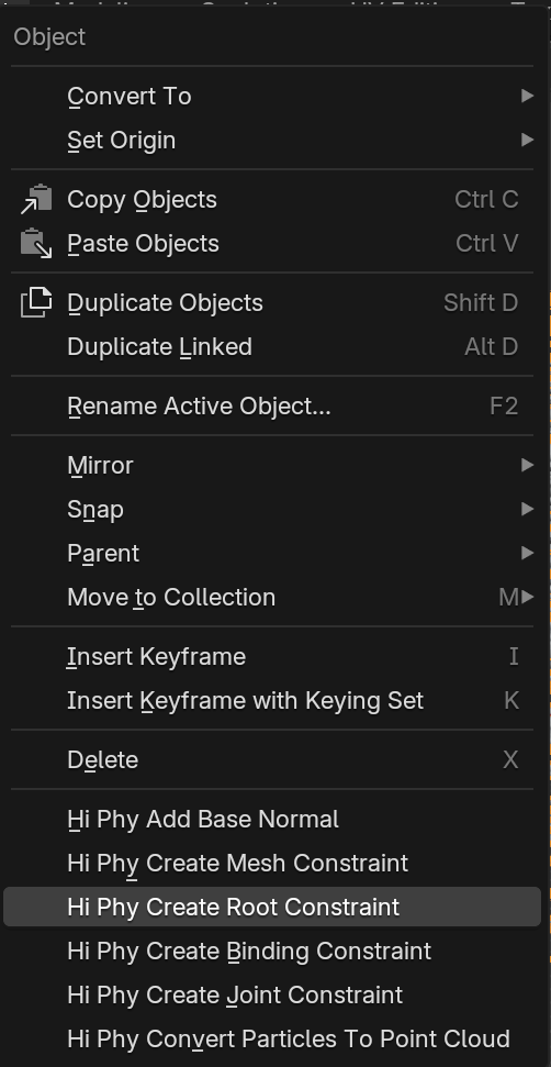
Root Constraint#
Given the required special base normal on the elastic rod objects, when constraining the elastic rod objects, we also need to constrain the base normal to prevent the elastic rods freely rotating along its edges. Root constraint constraints not only the position but the base normal of the elastic rods.
To create a root constraint in Blender, select the curves and the mesh you wish the root of the curves to anchor to, in Object Mode, choose, Hi Phy Create Root Constraint in the pop up menu. It will create a constraint that binds the position and base normal of the first vertex of each curve to the mesh.
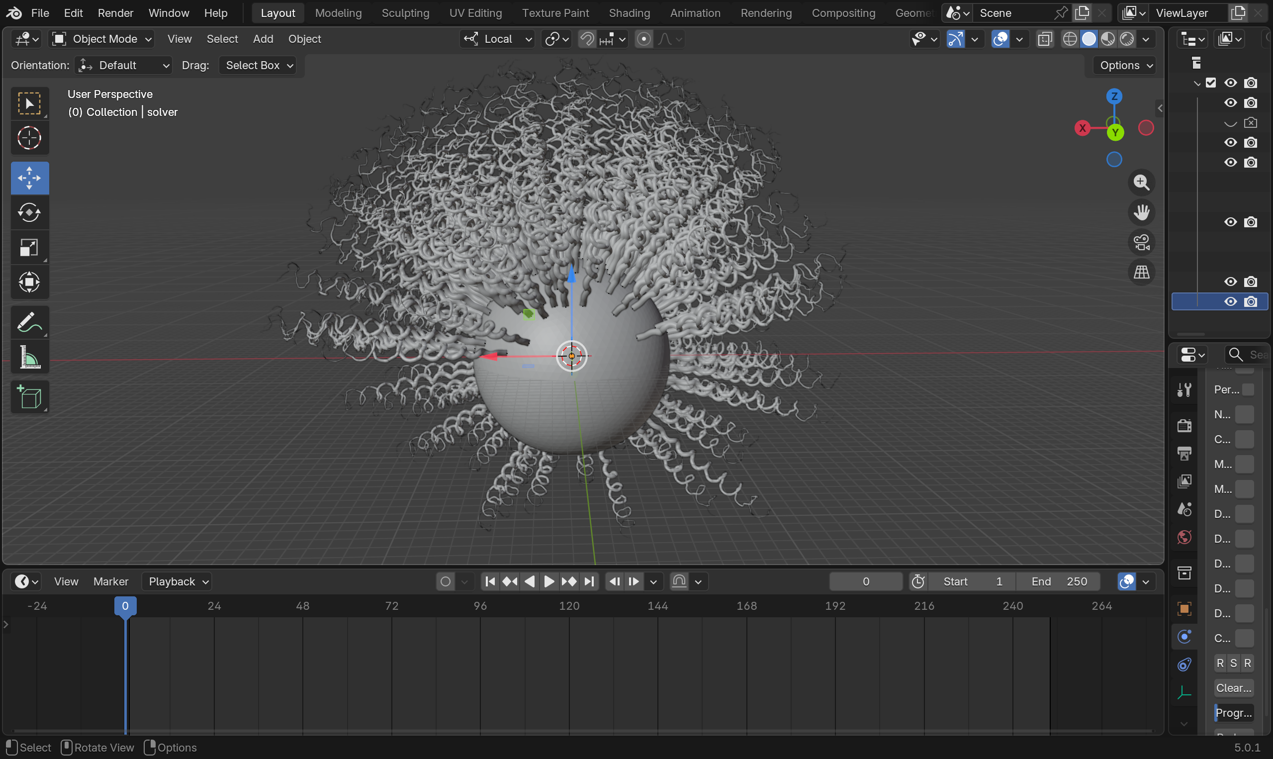
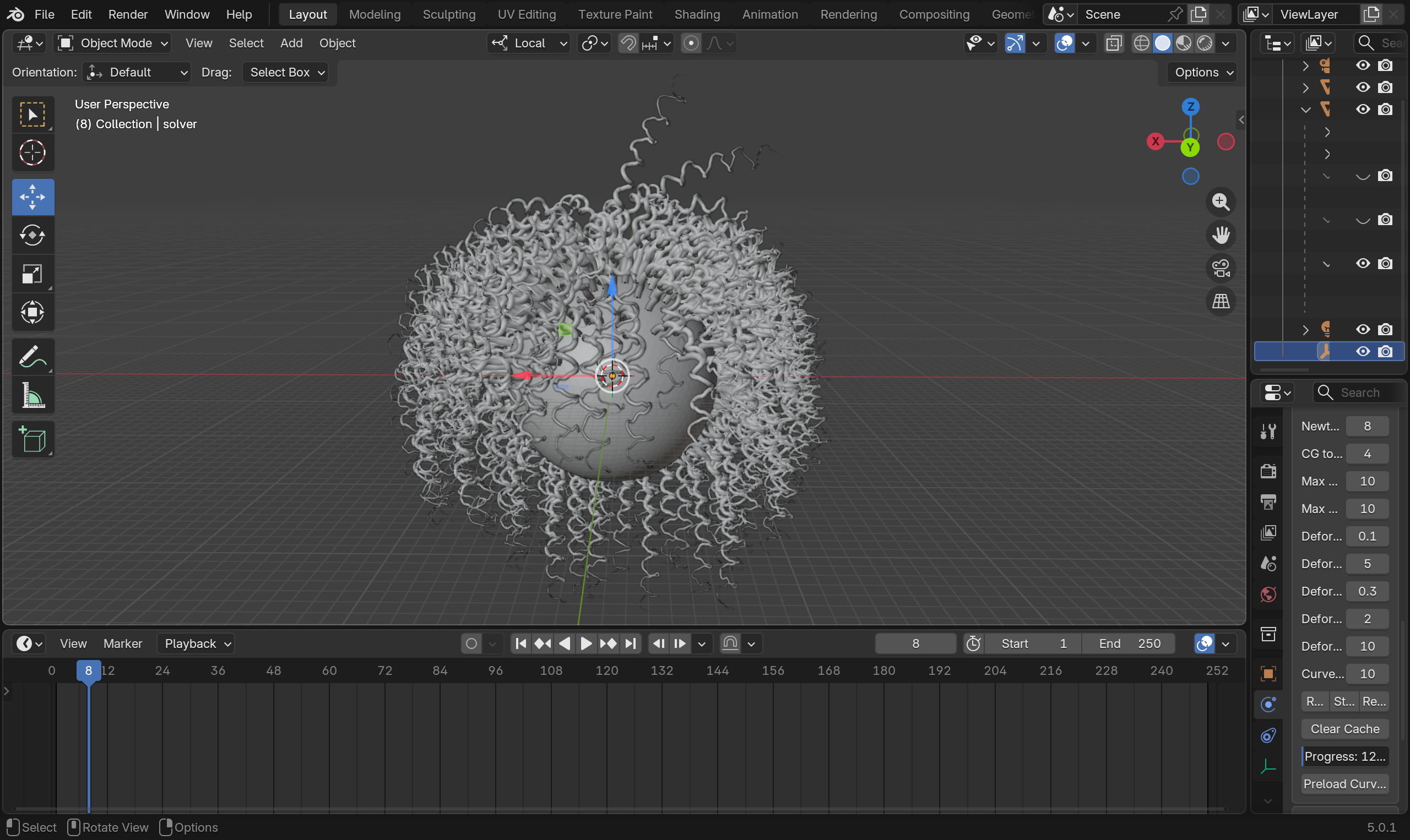
Preloading#
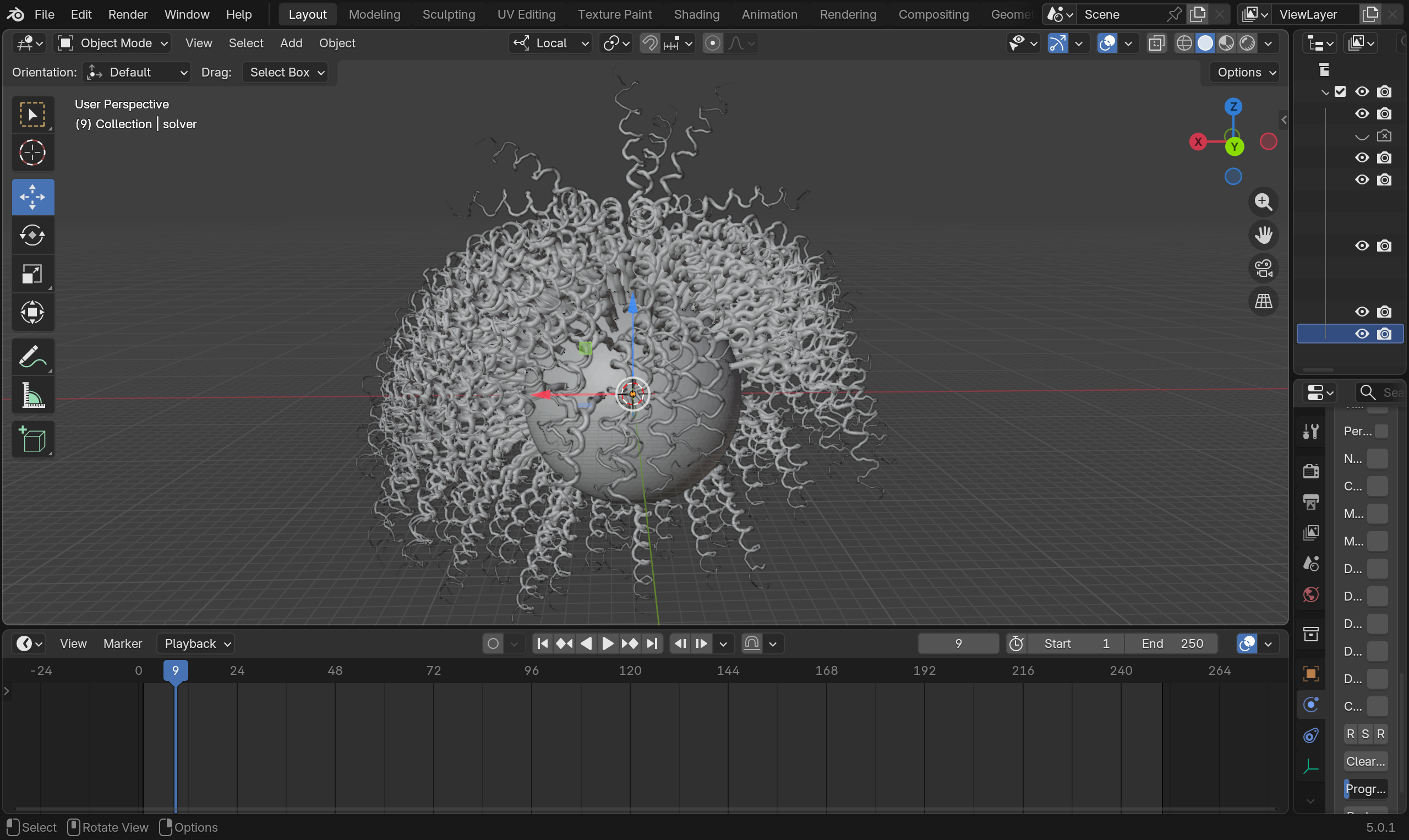
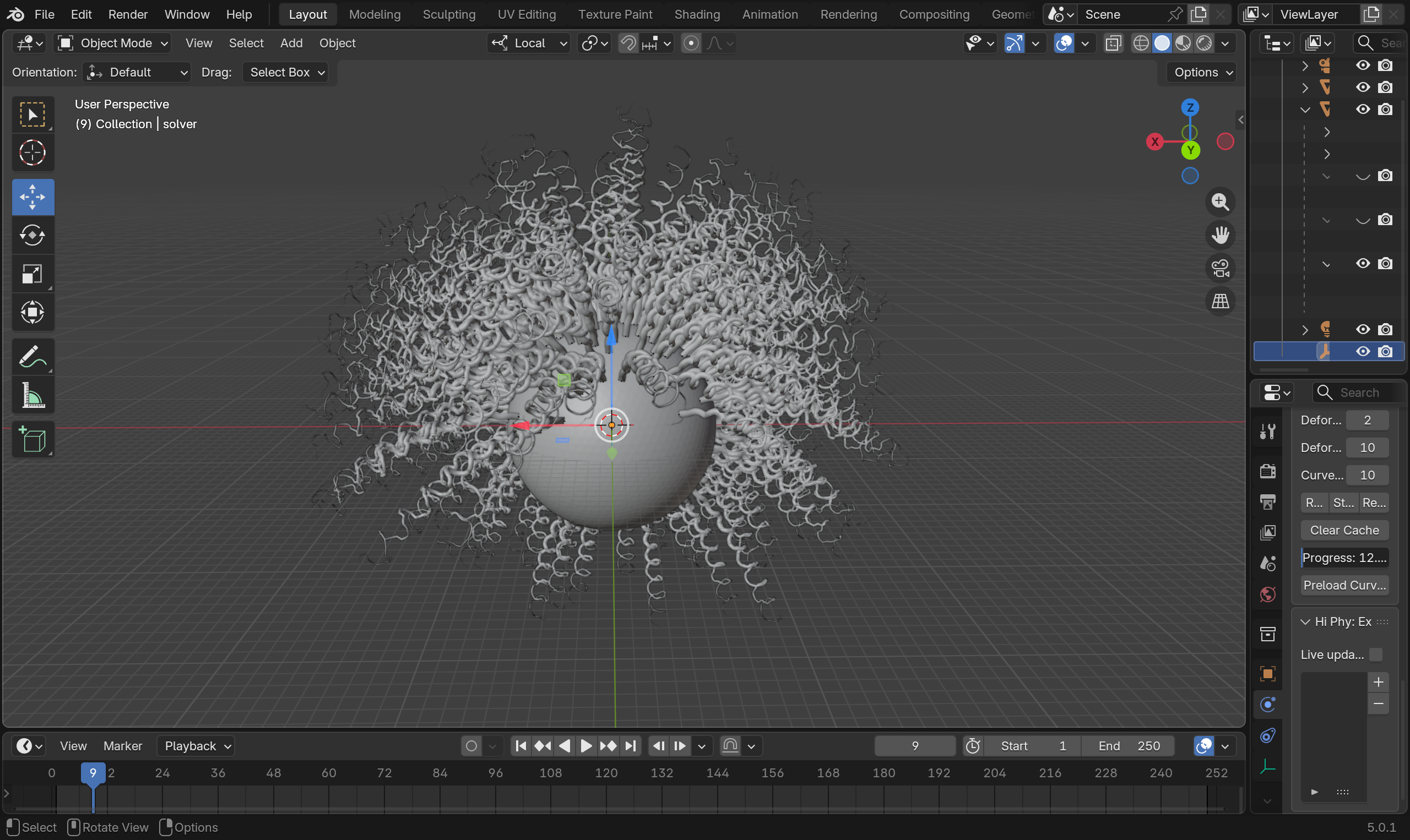
Under gravity and other external forces, elastic rods can undergo large amount of deformation and fails to maintain its designed shapes. The preloading process computes the rest shape that compensates the external forces, so the elastic rods can maintain it's designed shape. In contrast to using target shapes which can create unnatural motions, preloading creates more fluid results. However, preload to full can result in a floaty motion. It is advised to use a map for Preloading Percentage to preload less on the root or the rods and more on the tip the rods.
Preloading can only maintain the static designed shape. For hitting key shapes in motion, target shapes is still the best way to achieve that.
Preloading process modifies the rest shape object. Similar to the restriction on the simulation object, if user wish to use the preloading process, please make sure there is no modifier stack on the rest shape that changes the vertex positions or the topology.
Preloading curves button lives on the solver object. The preloading process gradually increases the force on the curves in the number of steps dictated by the curve preloading substeps. curve preloading substeps also defines the resolution of the Preloading Percentage parameter. By default, the preloading process takes 100 substeps, so Preloading Percentage has an effective resolution of 0.01.
Continuous Time Collision#
Unlike meshes, curves are line segments that do not have a self-intersecting state. However, during simulation, curves can still pass each other. In the case of curves, such scenario will not lead to a self-intersecting invalid state for the simulator. Therefore, we allow user to turn off continuous time collision for elastic rods as a global solver setting.
Examples#
You can find the an example file for elastic rod simulation here.
You can find the an example file for elastic rod preloading here.
Settling before preloading
Settling after preloading
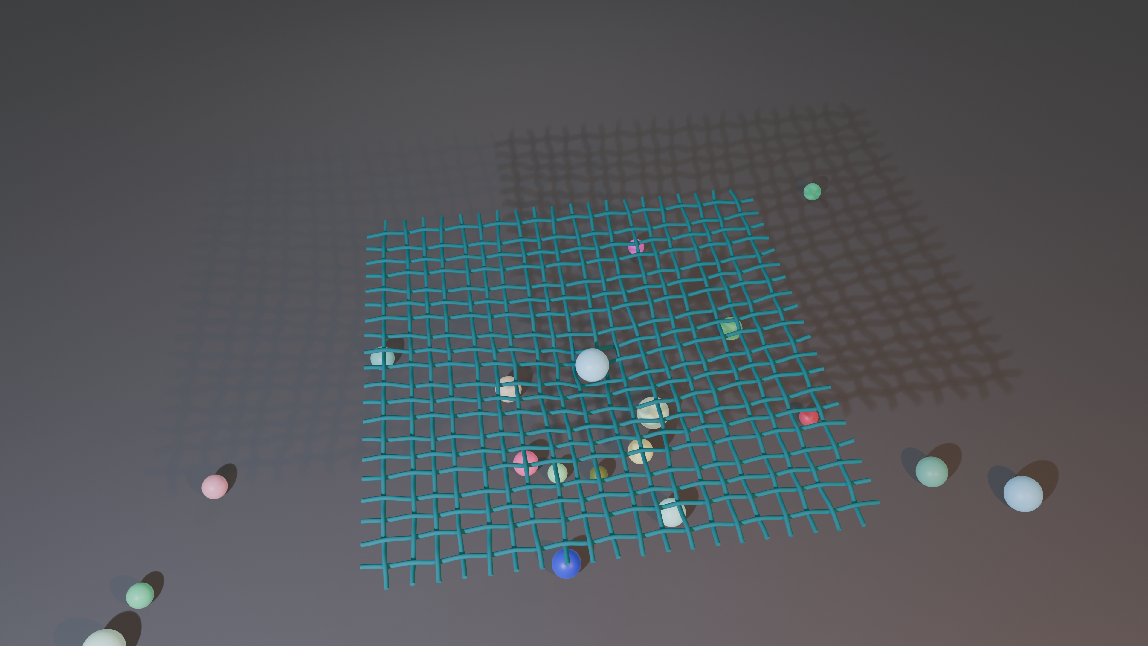
An example of coupling elastic rod and affine body can be find here.
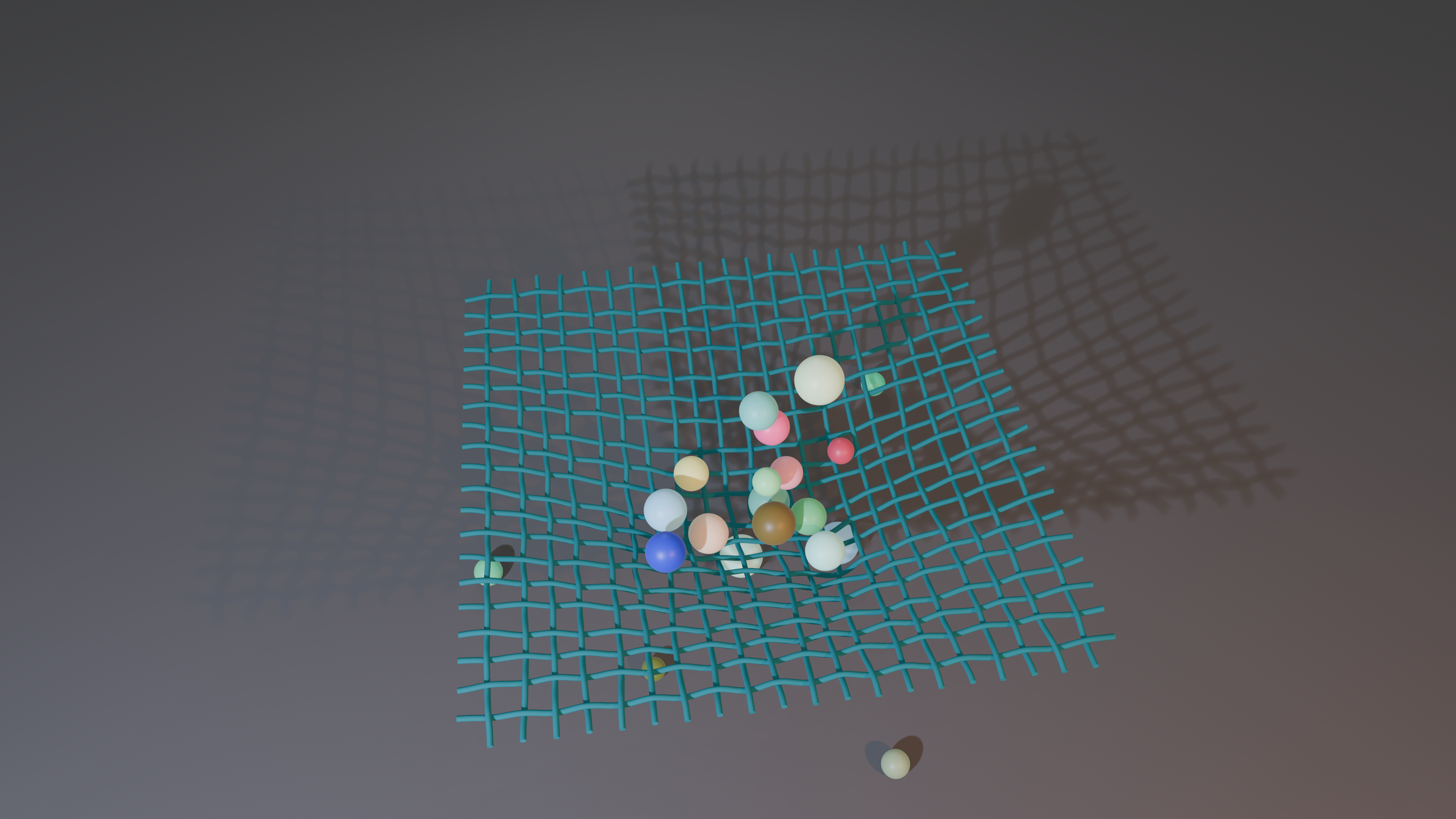
HiPhyEngine is able to accurately resolve all collisions. It allows affine bodies to slide between the elastic rods gaps. Despite of the high velocity impact, the weave pattern of the rods is maintained from HiPhyEngie's intersection free guarantee. In this example, we also demonstrate how to use geometry node on the driven shape to upsample the simulation results for rendering.