Tailor#
In this example, you will learn how to HiPhyEngine to tailor a sleeveless shirt for simulation.
To create the patterns, you can follow the youtube video here.
We will start with the Blender file here. The file already contains the cut patterns, we will only demonstrate how to use HiPHyEngine to tailor the cloth.
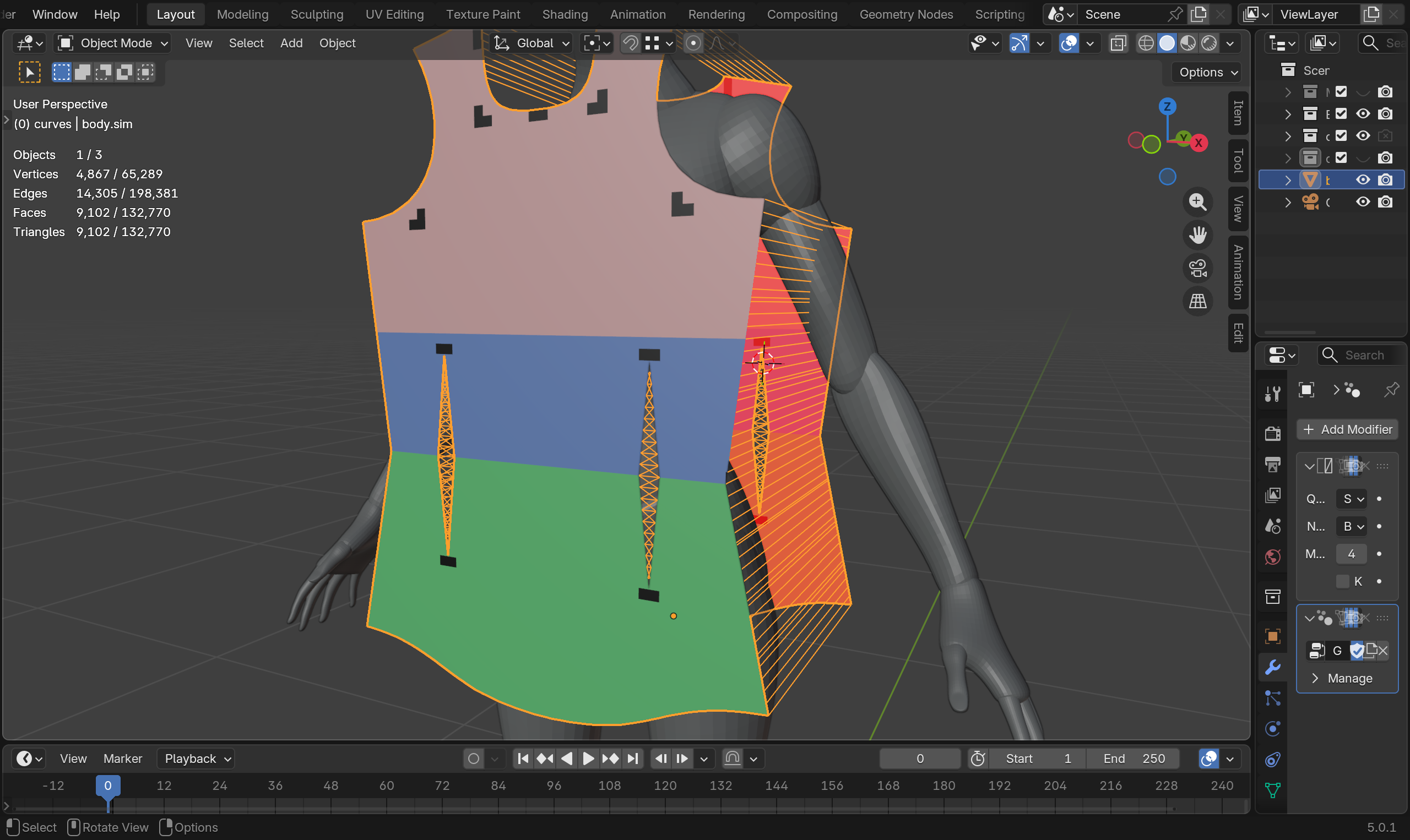
Stitching patterns
In the YouTube video, a simple point to point stitch was used. However, HiPhyEngine has continuous time collision, and point to point collision's 1D structure is unstable and will lead to jittering. We used an additional criss cross stitch to maintain the stitch structure. User can compare the two different stitches for stability if interested.
Step 1: Setup Solver#
-
Create an empty plane axis, rename it solver, goto the physics panel, turn on HiPhy, select Lagrangian Solver
-
Change the Newton tolerance to 4. (4 is enough for this example)
-
Change the Solver Scale to 100. (This converts the scene unit (m) to solver internal unit (cm))
-
Change the End Frame to 100.
Solver Scale
To get reasonable simulation result, the scene needs to be modeled in physical scale. The internal unit of HiPhyEngine is cm. The scene unit can be anything you want. To convert the units, Solver Scale is used to convert between the two. In this case, 100, from meters to centimeters. However, there is a class of parameters in HiPhyEngine are in Model Unit, such as all the collision distances. Model Unit is the unit of the scene. It is designed so that user can set collision distance by directly measure their scene without performing any conversion. You can find more details on Solver Scale and Model Unit here
Step 2: Setup Collider#
-
Select GEO-primitive_female_realistic
-
Add a Triangulate modifier and check the Keep Normals.
-
Goto the physics panel, turn on HiPhy, select Collider
-
Choose the solver object for the Solver parameter.
-
Set inner thickness to 0.001 (1mm).
-
Set outer thickness to 0.001 (1mm).
-
Set friction to 0.01. (For tailoring, we want the fabric to freely slide along the body)
Step 2: Setup Cloth#
The cloth simulation mesh is pre-provided as body.sim. Though the simulation parameters has not been setup yet.
To use the UV panel model, user will need to provide the hiphy_cloth_uv attribute. However, the cloth panel is perfectly flat and therefore we can directly use the local coordinate the cloth panel to the hiphy_cloth_uv attribute, by using a simple geometry node.
- Adding the following geometry node
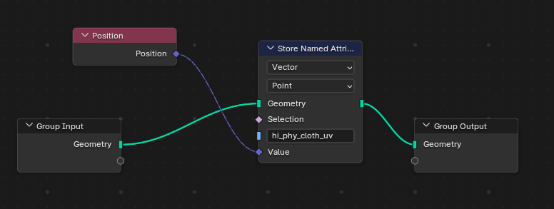
-
Add a Triangulate modifier and check the Keep Normals.
-
Goto the physics panel, turn on HiPhy, select Cloth
-
Choose the solver object for the Solver parameter.
-
Set inner thickness to 0.0002 (0.2mm).
-
Set outer thickness to 0.0002 (0.2mm).
Step 3: Setup Constraints (stitches)#
There are two different types stitches we will use here. The pin stitches that will pull the constraint vertices as close as possible, and The cross stitches that try to keep the vertices at some distance to maintain a structure.
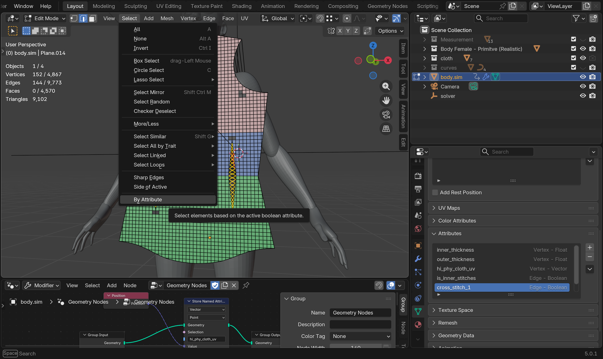
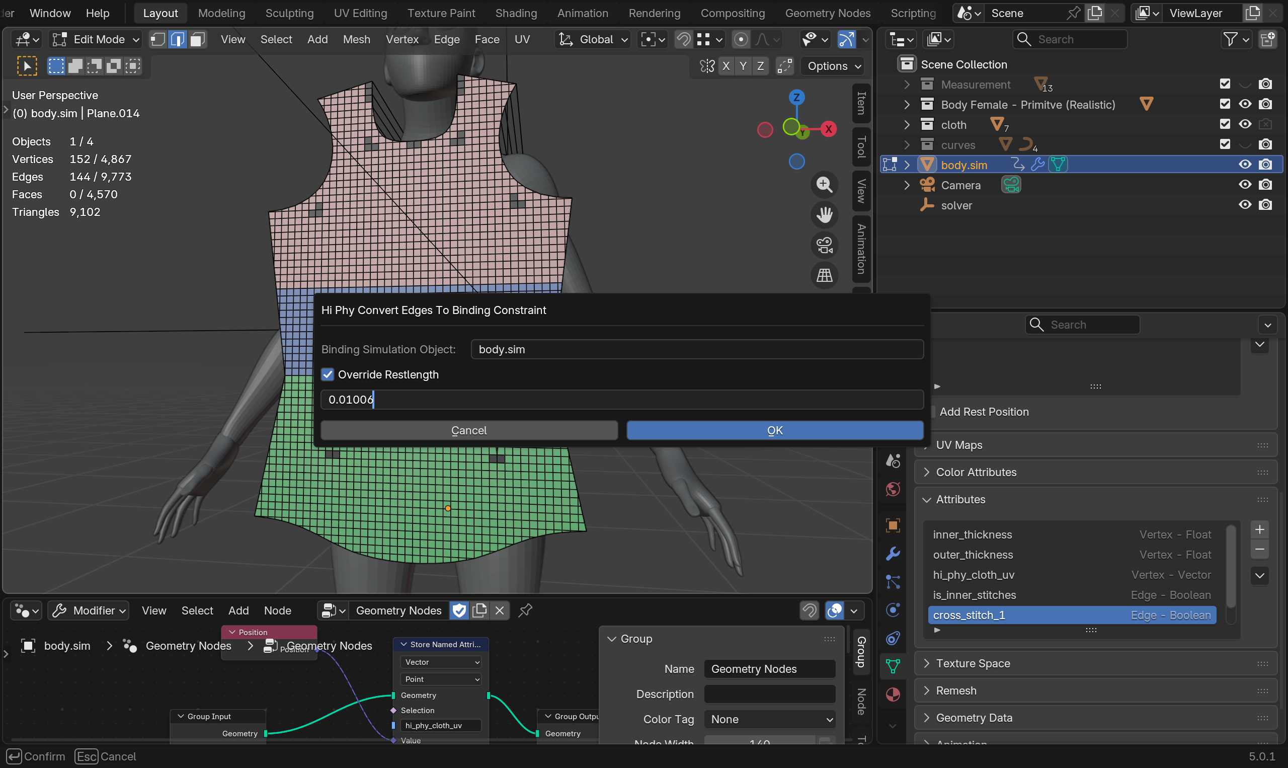
- Select body.sim goto Edit, Edge selection mode. The cross stitches should already been selected. If not, select attribute cross_stitches_1 in the data->attribute panel, then select->by attribute. Make sure all other edges are deselected.
-
With the cross stitches selected, right click->attribute->HiPhy Constraints->HiPhy Convert Edges to Binding Constraints.
-
Check Override Restlength and Set the rest length to 0.01006m.
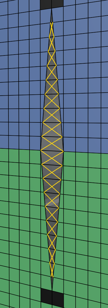
Cross Stitches Length
The cross stitches length is set to 0.01006m because the edges face of the fabric is 0.01005m, we are going to set the ping stitches rest length to 0.0005m (0.5mm). By Pythagorean rule, the diagonal of the triangle the edge the ping stitches will form is about 0.01006m.
- Rename the newly created constraint to cross.stitches
-
Select body.sim goto Edit, Edge selection mode. With cross stitches edges selected, goto Select, Invert. This will selected all non cross stitches edges.
-
With rest of the edges selected, right click->attribute->HiPhy Constraints->HiPhy Convert Edges to Binding Constraints.
-
Check Override Restlength and Set the rest length to 0.0005m (0.5mm).
HiPhy Convert Edges to Binding Constraints
HiPhy Convert Edges to Binding Constraints will only convert stray (edge that has no faces connected to it) to binding constraints.
Step 4: Animate Constraints#
If you run the simulation now, it will fail due to how fast the constraints are pulling the fabric onto the body. To allow the fabric to stitch in a more physically correct way, we will need to animate the constraints and parameters.
The animation will be in two stages: stitching and dripping. In the stitching stage, we will not have any gravity, only the stitching pulling the fabric together. In the dripping stage, gravity will be added, and let the cloth reach equilibrium.
-
Key body.sim's Gravity to (0, 0, 0) from frame 0 to 20. (0, 0, -980) from frame 21 to 40
-
Key compression stiffness and stretch stiffness of the two stitch constraints to 0 to 10000 from frame 0 to 20 then 100000 at frame 40.
That's it! Once you ran the simulation you will see the shirt stitches together!
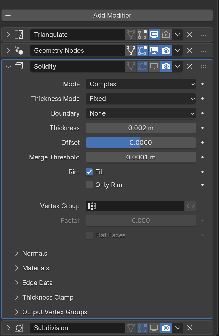
Step 4: (Optional) Setup Cloth for Rendering#
HiPhyEngine requires the cloth mesh to be triangulated, while for rendering, subdivision surfaces is best used with quads. We will show how to set up a simple modifier stack to allow rendering the subdivided quad cloth mesh instead of the triangulated simulation mesh.
-
body.sim, add a solidify modifier and a subdivision surface
-
Turn off the realtime toggle for the solidify modifier and the subdivision surface modifier.
-
Turn off the rendering toggle for the triangulate.
Modifier toggle trick
The modifier toggle trick allows the triangulation only kicks in, in viewport for simulation export, while the rendering will use a different modifier stack. If user want to see the effect of the rendering modifier stack in viewport. The proper way is to use a driven shape
- solidify modifier to Complex Mode, Fixed Thickness, change the Thickness to 0.002
Step 4 Alternative: (Optional) Driven Shape Setup For Rendering#
Limited by Blender Python API HiPhyEngine cannot properly integrate itself into the geometry node/modifier stack. To over come this, driven shape can be used.
driven shape is used as a puppet shape to bring back the simulation cache. Any modifiers can be applied on top of it without impact the simulation.
-
Duplicate body.sim to body.driven. Turn off Hi Phy from the Physics panel, and delete the duplicated solver object.
-
Goto body.sim's Hi Phy panel, select body.driven as the driven shape.
-
Add a solidify modifier and a subdivision surface to body.driven
Now those modifiers can be turned on in the view port for body.driven without restriction.
The final Blender file can be find here.